1 -
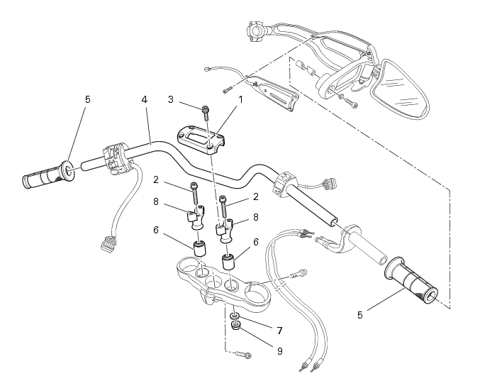
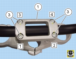
Handlebar
1
U-bolt
2
Screw
3
Screw
4
Handlebar
5
Twistgrips
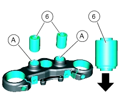
6
Spacer
7
Washer
8
Lower U-bolt
9
Nut
Parts catalogue
1100
HANDLEBAR AND CONTROLS
1100S
HANDLEBAR AND CONTROLS
Caution
Bold reference numbers in this section identify parts shown in this exploded view diagram. These parts do not appear in the
figures near the text.
Removing the handlebar
Operations
Reference - See Section
Remove the right and left hand guards
E 1,
Removing the hand guard - rear-view mirrors
Remove the throttle control
F 1,
Disassembling the throttle control
Remove the right and left switches
P 5,
Checking the indicators and lighting system components
Remove the front brake control
F 3,
Removing the front brake master cylinder
Remove the clutch hydraulic control
F 2,
Removing the clutch master cylinder assembly
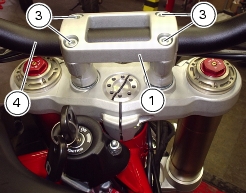
Release and remove the screws (3) of the clamp (1).
Remove handlebar clamp (1).
Remove the handlebar (4) from its seat in the steering head.
Slide handgrips (
5
) out of handlebar (4).
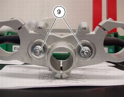
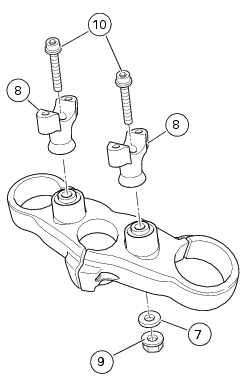
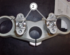
Holding nuts (9), loosen screws (2) and remove lower U-bolts (8) from steering head.
Unscrew the retaining screws (2), remove the lower clamps (8) and washers (7).
Refitting the handlebar
Slide handgrips (
5
) back on handlebar (4).
If spacers (6) were removed from steering head, lubricate them using silicone oil (spray).
Set spacers (6) fully home, axially with respect to holes (A) on steering head, positioning them as shown.
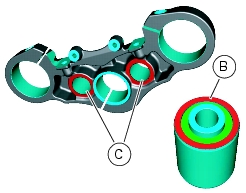
Caution
Spacers (6) must be installed onto outer ring (B) and reaction should be made on surfaces (C), in the bottom section of the
steering head.
At the end of this operation, clean any exceeding lubricant.
Fit the lower U-bolts (8) on the steering head.
Start the screws (2) on clamps (8); tighten nuts (9) with washers (7).
Tighten screws (2) to the specified torque (Sect. C 3,
Frame torque settings
) holding nuts (9).
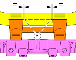
Fit handlebar (4) in its seat onto lower U-bolts (8).
Fit and position the handlebar so that markings (A) are at the same distance from lower U-bolt and are flush with U-bolt surface.
Apply recommended grease on the thread and underhead of the screws (3).
Refit clamp (1) and start the screws (3).
Tighten the screws (3) to the specified torque (Sect.
C 3,
Frame torque settings
), comply with sequence 1-2-3-4-1-2, as shown.
Operations
Reference - See Section
Install the front brake control
F 3,
Refitting the front brake master cylinder
Install the right and left switches
P 5,
Checking the indicators and lighting system components
Install the throttle control
F 1,
Reassembling the throttle control
Install the clutch hydraulic control
F 2,
Refitting the clutch master cylinder assembly
Refit the right and left hand guards
E 1,
Refitting the hand guard - rear-view mirrors