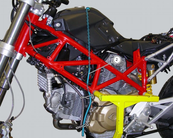
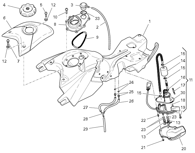
2 -
1
2
3
4
5
6
7
8
9
10
11
12
13
14
15
16
17
18
19
20
21
22
23
24
25
26
27
28
29
30
31
32
33
Parts catalogue
Caution
Bold reference numbers in this section identify parts shown in this exploded view diagram. These parts do not appear in the figures near the text.
Removing the fuel tank
 
Loosen and remove tank plug (4).
Loosen the screws (7) and remove tank (6) cover with washers (12).
Unscrew the screws (31) and remove the bracket (32).
Disconnect the rear turn indicators and number plate light wiring (Sect. P 1, Arrangement of wiring on frame).
Disconnect the fuel sensor (A) from the main wiring.
Loosen screw (B) and remove the light and injection relays.
Release main wiring from tank (1) by opening the metal clamps (C).

 Warning
Ensure that tank (1) is empty before removing the flange cover (20).
 
Loosen nuts (21), remove the flange cover (20) and disconnect the quick-couplings (13) from the flange.

 Warning
Loosen the special screw (D), holding the threaded insert located on tank top part with a 5 Allen wrench.
Remove the tank (1) from the vehicle.
Removing the tank plug
Remove the tube (2) of breather valve (3).
Release the breather valve (3) turning it counter clockwise and remove it from filler (8).
Unscrew the retaining screws (10) of the filler (8) and keep O-ring (9).
Refitting the tank plug
Suitably grease the O-ring (9).
Refit the filler (8) into its seat on tank and tighten screws (10) to the specified torque (Sect. C 3, Frame torque settings); proceed with sequence 1-2-3-4-5-6-7.
Fit the new O-ring (33) onto breather valve (3).
Fit breather valve (3) into its seat on filler (8) and turn clockwise to tighten it fully home.
Fit the tube (2).
Removing the tank flange
Unscrew the screws (19) and remove the flange (11) from the fuel tank.
Remove the flange (11) from the tank.
Collect the O-ring (30).
Release the clamps (15) at the fuel filter (14) with the suitable tool available on the market.
Detach the filter from the connection hoses and replace filter.
On refitting, clean off any build-up or scale accumulation from all components.
Caution
Fit the new filter. The arrow on the casing must be pointing to the flange.
Note
The spare flange comes complete with fuel pump and pressure regulator. If any one of these components is malfunctioning, replace the complete flange.
Refitting the tank flange
Fit the flange with O-ring (30). Grease the O-ring and reverse the removal procedure to refit.
Tighten the screws (19) to the specified torque (Sect. C 3, Frame torque settings).
Refitting the fuel tank
If the tank parts were separated, reposition all parts as shown, in particular: tighten the screws (A), (B) and (C) to the specified torque (Sect. C 3, Frame torque settings).
Set the tank (1) fitting the front retainers in the rubber blocks on frame.
Connect the quick-couplings (13) to the flange, refit the flange cover (20) and tighten nuts (21) to the specified torque (Sect. C 3, Frame torque settings).
Lock main wiring to tank (1) by tightening the metal clamps (C).
Install the light and injection relays and start screw (B) in its thread.
Connect the rear turn indicators and number plate light wiring (Sect. P 1, Arrangement of wiring on frame).
Connect the fuel sensor (A) to the main wiring.

 Warning
Tighten the special screw (D), holding the threaded insert located on tank top part with a 5 Allen wrench.
Refit bracket (32) and tighten screws (31).
Refit tank (6) cover, start the retaining screws (7) in their thread with washers (12).
Tighten the screws (7) and (31) to the specified torque (Sect. C 3, Frame torque settings).
Tighten the fuel plug (4).
 
Routing of the fuel tank breather and drain tubes
Fuel lines layout