
|
5 -
|
|
1
|
|
3
|
|
5
|
|
7
|
|
9
|
|
11
|
|
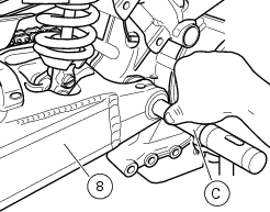
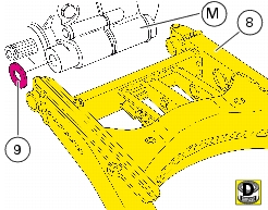
Remove the shock absorber and the linkage from the rear swingarm
|


|
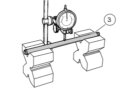
Shims on left side
|
Shims on right side
|
|
|
One 0.10 mm shim
|
||
|
One 0.10 mm shim
|
One 0.10 mm shim
|
|
|
One 0.10 mm shim
|
One 0.20 mm shim
|

|
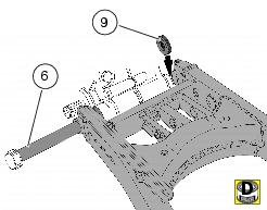
Refit the shock absorber and the linkage to the rear swingarm
|
|