6 -
1
2
3
4
5
6
7
8
9
10
11
12
13
14
15
Parts catalogue
Caution
Bold reference numbers in this section identify parts shown in this exploded view diagram. These parts do not appear in the figures near the text.
Removing the rear brake system
The components listed below must first be removed to allow removal of these components.
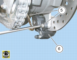
Remove the screw retaining the hose to the rear brake cylinder and the seals
Rear brake caliper and master cylinder
Release and remove the special screw (1) retaining the hose (4) to the rear brake caliper and the seals (2).
Note
The pictures show swingarm removed from vehicle but described procedures are possible even with swingarm fitted to the vehicle.
 
Please refer to exploded view in Sect. G 5, Rear swingarm.
Unscrew the screws (A) and remove heat shield (B).
Loosen screws (C) and remove the lower chain slider (D).
Remove tube (4).
Unscrew the two screws (5) securing the rear brake caliper to the caliper holder plate and remove the brake caliper (6).
Note
Please refer to "Checking brake pad wear. Changing brake pads” (Sect. D 4) for brake pads changing procedure.
Caution
Critical safety components. The brake manufacturer recommends that you do not attempt to service the internal components of brake calipers and master cylinders. Incorrect overhaul of these critical safety components can endanger rider safety.
 
Maintenance operations on these units are limited to:
Caliper: brake pads, fasteners and bleed unit;
Master cylinder: control pedal, bleed unit, reservoir and component parts (Sect. F 4, Rear brake control).
Please refer to the exploded view at the beginning of this Section for indications on the replacement of the above components.
Rear brake disc
Remove the rear eccentric hub (Sect. G 5, Removing the rear eccentric hub).
Unscrew the four screws (13) securing the brake disc to the wheel shaft and remove the rear brake disc (10).
If they need replacing, unscrew the screws (12) on the eccentric hub and remove the reference pins (11). Smear with recommended threadlocker upon reassembly
The brake disc must be perfectly clean, with no rust, oil, grease or other dirt and no deep scoring.
For brake disc service limit, please see Sect. C 1.1, Rear wheel.
Refit the rear brake disc (10), tighten screws (13) to the specified torque (Sect. C 3, Frame torque settings) following a 1-2-3-4 sequence, applying recommended threadlocker onto screws (13).
Refit the rear eccentric hub as described in (Sect. G 5, Refitting the rear eccentric hub).
Refitting the rear brake system
When changing the brake hoses or removing one of the rear brake system components, care must be taken to position the connectors on the brake cylinder and the caliper at the correct angles.
Warning
Incorrectly positioned hoses can cause brake faults and interfere with moving parts. Correct position is shown in the diagram.
Fit the special copper gaskets (2) to the connector when securing the brake hose to the brake caliper and cylinder.
Arrange the connectors at the correct angles and then tighten the special screws (1) to the specified torque (Sect. C 3, Frame torque settings).
Note
The pictures show swingarm removed from vehicle but described procedures are possible even with swingarm fitted to the vehicle.
 
Route the rear brake line (4) under swingarm and fasten it to speed sensor cable (F) using tie (E).
Lay out line (4) and cable (F) inside swingarm slot.
Install the lower chain slider (D) and fasten with screws (C) after smearing them with recommended threadlocker.
Install heat shield (B) and smear screws (A) with recommended threadlocker; tighten screws (C) and (A) to the specified torque (Sect. C 3, Frame torque settings).
Fit the rear brake caliper (6) to the brake disc matching the holes in the caliper plate.
Apply some grease to the screws (5) and tighten to the specified torque (Sect. C 3, Frame torque settings).