|
6.1 -
|
|
2
|
|
4
|
|
10
|
|
11
|
|
14
|
|
15
|
|
16
|
|
17
|
|
18
|
|
19
|
|
20
|
|
23
|
|
24
|


|
-
|
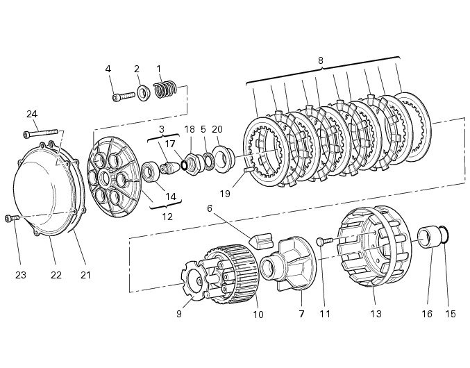
two driven plates (G), thickness 1.5 mm;
|
|
-
|
|
-
|
one spring plate (L), thickness 1.5 mm, see position in cross-section;
|


