|
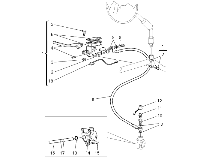
8
|
|
10
|
|
11
|
|
12
|
|
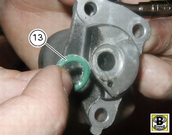
13
|
|
15
|
|
17
|
|
18
|