|
-
|
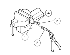
the key head -including the electronic circuit transmitting stored secret code- can be removed and fitted to a different key body if motorcycle locks and ignition lock are changed;
|
|
-
|
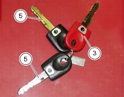
it is recommended the red key be used only for programming the immobilizer system. Use the black keys to start the engine. Keep the red key in a safe place.
|
|
-
|
|
-
|
|
-
|
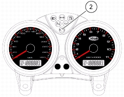
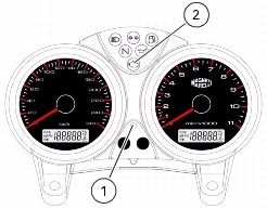
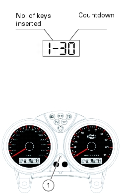
turn the key to ON so to switch on the instrument panel. The multifunction display will show the number of inserted keys (here "1") and a countdown starting from 30. Important: ensure that the ignition switch was to OFF for at least thirty seconds before performing the above
|
|
-
|
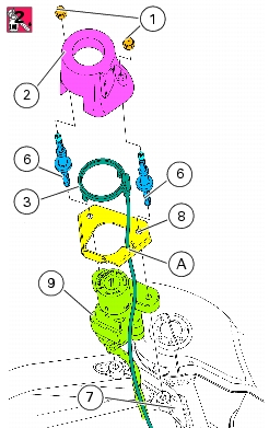
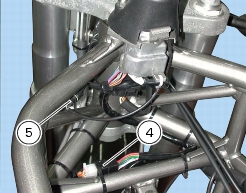
remove the red key, insert a black key (5) and set the switch to ON within the next 15 seconds (display shows the number of keys inserted, in this instance 2, with the countdown from 30 to 0 at the side)
|
|
-
|
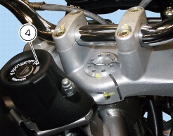
remove the black key, insert the red key and set the switch to ON within the next 15 seconds (display shows the number of keys inserted, in this instance 4, with the countdown from 30 to 0 at the side)
|
|
-
|
ensure that the countdown has begun and set the key to OFF before it reaches zero. The LED (1) on the instrument panel will flash to indicate successful programming.
|
|
-
|
leave the key positioned to ON for 5 to 15 seconds (not less than 5 and not more than 15 seconds) to allow data transfer from the decoder to the engine control unit and then turn the key to OFF
|

|
-
|
if the led flashes for two seconds, it means that the immobilizer is not programmed, maybe because the programming procedure has not been strictly followed. Repeat the programming procedure from the start.
|
|
-
|
a series of short flashes indicates the number of programmed keys. If programming has been successfully completed, the led must flash three times (a red key and two black keys used for programming)
|
|
1
|
|
3
|
Now enter the electronic code indicated on the CODE CARD which is given to the customer on motorcycle delivery by the dealer.
the EOBD light starts flashing. count a number of EOBD light flashes which is as the first digit of the electronic code. Completely turn the throttle twistgrip and hold it open. The EOBD light stays fixed on for four seconds: it means that the first digit of the emergency code has been acknowledged. If the throttle twistgrip is untouched, the EOBD light will flash 20 times, then it will stay permanently on. In this case the whole procedure should be repeated from step 1. |
|
6
|
After releasing the throttle twistgrip and if the entered code is correct, the EOBD light will flash for 4 seconds to indicate that the immobilizer is now disabled. Then it turns off. It will immediately turn off if the engine is started before 4 seconds have elapsed.
|
|
7
|
If the code is NOT correct, the EOBD light stays on. Repeat the procedure from step 1. There is no limit, the procedure can be repeated as many times as needed.
|