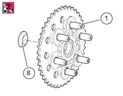
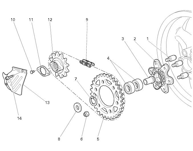
8 -
1
2
3
4
5
6
7
8
9
10
11
12
13
14
Spare parts catalogue
Caution
Bold reference numbers in this section identify parts shown in this exploded view diagram. These parts do not appear in the figures near the text.
Final drive inspection
Check the wear of the final drive. Visually inspect the front (12) and rear (5) sprockets. If the tooth profile is as shown by the broken line in the figure, change the sprockets.
To check chain (9) wear, stretch the chain and measure 16 links.
If the length (L) is greater than 256.5 mm, change the chain.
Caution
The rear sprocket (5), the front sprocket (12) and the chain (9) must all be changed together.
Removing the chain sprocket
Unscrew the screws (14) and take off the sprocket cover (13).
Slacken the chain (Sect. D 4, Adjusting chain tension).
Engage a low gear and unscrew the two screws (10) on the sprocket retaining plate (11).
Remove the plate (11) from the gearbox secondary shaft.
Slide the front chain sprocket (12) with the chain (9) off gearbox secondary shaft and take the chain off the sprocket.
Refitting the chain sprocket
Check that the splines of secondary shaft and sprocket are in perfect condition.
Wrap the chain (9) around the sprocket (12).
Fit the sprocket on the gearbox secondary shaft (B) as shown in the figure and push it past the shaft spline (A).
Insert the retaining plate (11) on the gearbox secondary shaft (B) and rotate it inside the recess (A) so that the plate holes (11) match the threaded holes in the sprocket (12); position the retaining plate with the rounded corner facing the sprocket.
Apply threadlocker to the thread of the screws (10).
Engage first gear.
Tighten the screws (10) to the specified torque (Sect. C 3, Frame torque settings).
Adjust chain tension (Sect. D 4, Adjusting chain tension).
Position the front sprocket cover (13) and tighten the screws (14) to the specified torque (Sect. C 3, Frame torque settings).
Removing the rear sprocket
 
Slide the complete rear sprocket flange (2) off the rear wheel.
Hold the pins (1) at the rubber cush pads steady and undo the nuts (6) retaining the sprocket to the flange.
Caution
The pins (1) have left-hand threads.
 
Remove the rear sprocket.
Refitting the rear sprocket
Make sure that all pins (1) are securely in place in the flange (2). If not so, unscrew the left-threaded pins, clean the threads and apply threadlocker to the thread with the larger diameter.
Tighten them to the flange to the specified torque (Sect. C 3, Frame torque settings).
Apply threadlocker to end threads of the pins (1).
Fit the new sprocket (5), hold the pins and tighten the nuts (6) to the specified torque (Sect. C 3, Frame torque settings).
Warning
Perform the procedure carefully. If any one pin is not tightened securely fully home into the flange before the nuts are tightened on the sprocket, the sprocket will be installed incorrectly, endangering rider and motorcycle safety.
 
Grease pins (1) and fit the rear sprocket flange (2) in the rear wheel hub, fit the pins in the relevant rear wheel cush drive rubbers (G).
Install the spacer (8) with the tapered end facing the rear sprocket flange.