1 -
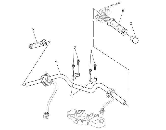
Handlebar
1
U-bolt
2
Blanking plug
3
Screw
4
Handlebar
5
Twistgrips
Spare parts catalogue
Handlebar and controls
Caution
Bold reference numbers in this section identify parts shown in this exploded view diagram. These parts do not appear in the
figures near the text.
Removing the handlebar
Operations
Reference See Section
Remove the throttle control
F 1,
Disassembling the throttle control
Remove the right and left switches
P 5,
Checking the indicators and lighting system components
Remove the front brake control
F 3,
Removing the front brake master cylinder
Remove the clutch hydraulic control
F 2,
Removing the clutch master cylinder assembly
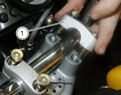
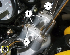
Release and remove the screws (3) of the clamps (1).
Remove both handlebar clamps (1).
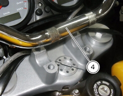
Remove the handlebar (4) from its seat in the steering head.
Please refer to the exploded view at the beginning of this section for handgrips (
5
) removal procedure.
Refitting the handlebar
Position the handlebar (4) to its seat in the steering head.
Position the clamps (1) to the handlebar.
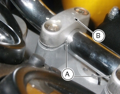
Caution
The arrow (B) on the back of the clamps must be facing the tank.
When fitting the handlebars, make sure the dots (A) lie in the same line as the seats in the steering head as shown in the figure.
Apply specified grease on the thread of the screws (3).
Tighten the screws (3) to secure the clamps (1).
Tighten the screws (3) to the specified torque (Sect. C 3,
Frame torque settings
).
Operations
Reference See Section
Install the front brake control
F 3,
Refitting the front brake master cylinder
Install the right and left switches
P 5,
Checking the indicators and lighting system components
Install the throttle control
F 1,
Reassembling the throttle control
Install the clutch hydraulic control
F 2,
Refitting the clutch master cylinder assembly