6 -
Checking protection and safety devices components
Checking the key-operated switch
Disconnect the key-operated switch (A) from the electric system (see chapter "Arrangement of wiring on frame" under Sect. P 1) and check for electric continuity of inner connections with a multimeter as follows:
set the ignition key to OFF and connect a multimeter to contacts (1) and (4) to check for electric continuity (Section P 9, How to use the multimeter to check electric systems on multimeter operation). Resistance value taken by the multimeter should be close to zero and, if available, a continuity beep should be heard.
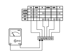
Turn the ignition key to ON and connect a multimeter to contacts (3) and (6) and then to (2) and (5) to check for electric continuity. Resistance value taken by the multimeter should be close to zero and, if available, a continuity beep should be heard.
Turn the ignition key to PARK and connect a multimeter to contacts (1) and (4) and then to (3) and (5) to check for electric continuity. Resistance value taken by the multimeter should be close to zero and, if available, a continuity beep should be heard.
Turn the ignition key to LOCK and connect a multimeter to contacts (1) and (4) to check for electric continuity. Resistance value taken by the multimeter should be close to zero and, if available, a continuity beep should be heard.
Note
The same test may be done using the “DDS” tester (Sect. D 5, DDS diagnosis instrument).
Checking the side stand switch
Remove switch from side stand (Sect. H 5, Removing the side stand) and disconnect it from the main wiring harness (refer to “Arrangement of wiring on frame” under Sect. P 1).
Use an analog or digital multimeter (Sect. P 9, How to use the multimeter to check electric systems) to check switch correct operation (see table).
Note
The same test may be done using the “DDS” (Sect. D 5, DDS diagnosis instrument).
l - s
s - n
Green/
Green
White
Green/
Yellow
Black
0 = Open contact
X = Closed contact
Checking the fuses
The main fuse box (1) is located on the right-hand side of the battery mount.
To access the fuses, open the fuse box cover. Fuse layout and amperage are shown on the cover.
Please refer to "Arrangement of wiring on frame” Sect. P 1 for ampere ratings.
Caution
Before changing a blown fuse with another equally rated fuse, trace and remove the cause of the fault.
 
A fuse is blown when its conducting filament (A) is broken.
Caution
To prevent short circuits, ensure that the ignition key is in the OFF position before changing a fuse.
Warning
Use only fuses with the specified amperage. Using fuses with the incorrect amperage may damage the electrical system and cause fires.
 
In addition to the fuses contained into the fuse box, the bike is also equipped with a 30A fuse positioned under the battery mount that protects the electronic regulator (Sect. P 2, Rectifier - regulator).