2.1 -
Lubrication system: oil pump
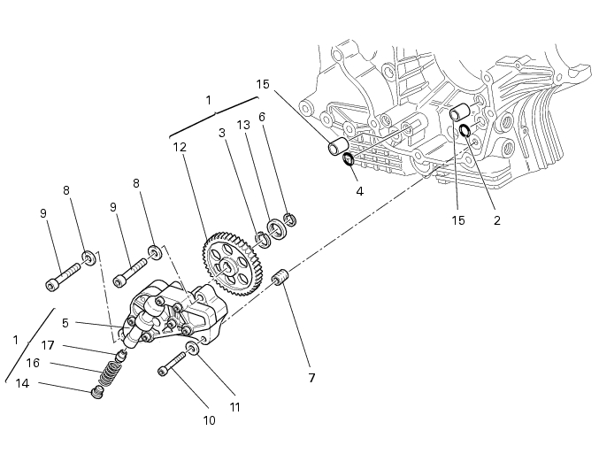
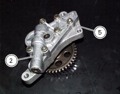
1
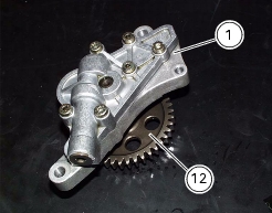
Complete oil pump
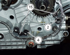
2
O-ring
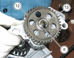
3
Circlip
4
O-ring
5
Pump body
6
Circlip
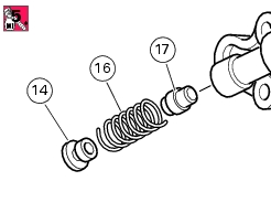
7
Reduction bush
8
Spring washer
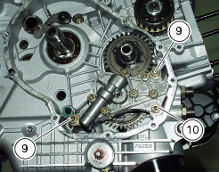
9
Screw
10
Screw
11
Spring washer
12
Pump control gear
13
Bush
14
By-pass valve cap
15
Centring bush
16
By-pass spring
17
Pressure-relief (by-pass) valve
Parts catalogue
1100
FILTERS AND OIL PUMP
1100S
FILTERS AND OIL PUMP
Caution
Bold reference numbers in this section identify parts shown in this exploded view diagram. These parts do not appear in the
figures near the text.
Removing the oil pump
Operations
Reference - See Section
Drain the circuit
D 4,
Changing the engine oil and filter cartridge
Remove the engine from the frame
N 1,
Removing the engine
Remove the clutch cover
N 6.2,
Removing the clutch cover
Undo and remove the screws (9) and (10) fixing the complete pump.
Remove the complete oil pump (1) and slide the two O-rings (2) and (4) and the two centring bushes (15) out of the casing.
Disassembling the oil pump gear
Vice the oil pump (1). Make sure not to damage the pump control gear (12).
Warning
Make sure that vice jaws are duly protected.
Remove plug (14) and slide out spring (16) and by-pass valve (17).
Check for proper operating conditions.
Remove the circlip (6), withdraw the bush (13) and remove the snap ring (
3
).
Remove the pump control gear (12).
Reassembling the oil pump gear
Insert pump driving gear (12), snap ring (
3
) and bushing (13) onto oil pump.
Fit the circlip (6) into its seat to lock the components in place.
Insert by-pass valve (17) and spring (16) into pump then tighten plug (14) to the specified torque (Sect. C 3,
Engine torque settings
) applying a medium-strength threadlocker.
Fit pump cover (2) to pump body (5) complete with gears.
Refitting the oil pump
Place the centring bushes (15) and the oil O-rings (2) and (4) at the oil ducts in the casing.
Place the oil pump on the casing and tighten the screws (9) and (10) to the specified torque (Sect. C 3,
Engine torque settings
).
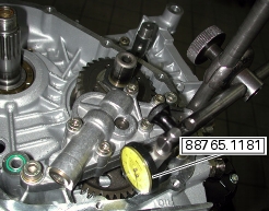
Secure dial gauge part no.
88765.1181
provided with a special pointer on the casing to check the meshing clearance with the crankshaft sprocket.
Bring dial gauge pointer in contact with one of the oil pump gear teeth and set the instrument to zero on this position.
Slightly move the gear to measure the clearance. Take four readings in diametrically opposite positions of the gear.
Clearance must be
0.10
mm.
Operations
Reference - See Section
Refit the clutch cover
N 6.2,
Refitting the clutch cover
Install the engine to the frame
N 1,
Reassembling the engine
Fill the system with fluid
D 4,
Changing the engine oil and filter cartridge
1