|
2
|
|
6
|
|
8
|
|
9
|
|
11
|
|
12
|
|
13
|
|
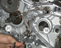
18
|
|
19
|
|
20
|
|
21
|
|
23
|
|
24
|
|
Remove generator cover and flywheel/generator assembly
|
|
|
Remove the clutch cover complete with clutch housing and primary drive gear
|


|
Fit the clutch cover complete with clutch housing and primary drive
|
|
|
Refit flywheel/generator assembly and generator cover
|