4 -
Checking the engine oil level
Check the engine oil level in the sight glass (1) on the RH side of the oil sump.
After switching off, allow several minutes for the oil to settle before checking the level. Check the level with the motorcycle perfectly vertical and with the engine hot (but stopped).
The level should be between the MIN and MAX marks. Top up if low. Remove the filler plug (2) and top up with the recommended oil.
Refit the filler plug.
Changing the engine oil and filter cartridge
Note
Change the oil when the engine is hot (but off). In these conditions the oil is more fluid and will drain more rapidly and completely.
 
Remove the drain plug (3) on the oil sump and allow the oil to drain off.
Warning
Dispose of oil and/or filter cartridges in compliance with environmental protection regulations.
 
Remove any metallic deposits from the end of the magnetic drain plug. Refit the drain plug complete with seal (A) to the sump.
Tighten it to the specified torque (Sect. C 3, Engine torque settings).
With a common filter wrench, remove the filter cartridge (4) from the oil sump.
Caution
Dispose of used cartridge. Do not reuse cartridges.
 
Grease the seal with engine oil and then fit the new cartridge (4).
Note
If you wish to skip this last check, fill the filter cartridge (2) with oil before installation and you will not need to top up level later.
Screw it in its seat and tighten to the specified torque (Sect. C 3, Engine torque settings).
Clean the oil mesh filter every second oil change.
Unscrew the outer plug (5).
Release and withdraw the mesh filter (7).
Clean the mesh filter with gasoline and compressed air. Care must be taken not to break the filter mesh.
Refit the mesh filter (7) and its seal (6) on the plug (5) and tighten to the specified torque (Sect. C 3, Engine torque settings).
Remove the filler plug (2) and fill with the recommended oil (Sect. C 2, Fuels and lubricants). Fill until the oil reaches the MAX mark on the sight glass.
Refit the filler plug (2). Run the engine at idling speed for several minutes.
Check for oil leaks. Check that the oil pressure light on the instrument panel switches off several seconds after the engine has been started. If this is not the case, switch off and trace the fault.
Switch off the engine and allow several minutes for the oil to settle. Check the oil level and top up to MAX mark, if necessary.
Refit any parts you have removed.
Checking valve clearances
Proceed as described under Section N 4.1, Checking and adjusting valve clearance.
With the valve in the rest position, slide a feeler gauge between opening rocker arm and shim to measure clearance.
Values must be as follows:
 
With the valve in the rest position, slide a feeler gauge between closing rocker arm and shim to measure clearance. Clearance must be within the specified limits:
 
If the clearances measured are outside the specified limits, measure clearance and adjust as required (Sect. N 4.1, Checking and adjusting valve clearance).
Adjusting valve clearances
Proceed as described under Section N 4.1, Checking and adjusting valve clearance.
Changing and cleaning the air filters
The air filter must be changed at the intervals indicated in the "Routine maintenance table" (Sect. D 3).
Raise the fuel tank (Sect. L 2, Removing the fuel tank).
Release the cover clips (1) on either side of the airbox.
Remove the cover (2).
Remove the filter cartridge (3) and replace.
Blow the filter cartridge with compressed air or replace it if unserviceable.
Caution
A clogged air filter will reduce air intake and engine power leading to increased fuel consumption, and cause a build up of deposits on the spark plugs. Do not run the engine without the air filter. Running the engine without a filter will draw impurities into the engine and may damage the engine.
 
Fit the filter cartridge into the filter box and refit all components previously removed.
Caution
If the vehicle is used in very damp or dusty conditions, the air filter cartridge must be changed more frequently.
Changing the brake fluid
Warning
Brake fluid will damage painted surfaces if spilled on them. In addition, it will cause severe injury if spilled on the skin or into your eyes. In the event of accidental contact with skin or eyes, wash the affected area with abundant running water.
Filling the front brake circuit
Undo the screws (1) and remove the diaphragm cover from the front brake reservoir (A).
Connect a clear hose to the bleed valve (2); put one end of the hose into a container on the floor.
Suck the oil up from the reservoir (A).
Fill reservoir (A) with fresh oil up to MAX level.
Pump up two or three times with the lever to pressurize the circuit.
Keep the lever pulled toward the handgrip.
Loosen the bleed valve (2) so that oil flows off.
Warning
When filling up, keep oil level above MIN mark to avoid air bubbles into the circuit.
 
Let oil flow off from the bleed valve (2) until of different color.
Tighten the bleed valve to the specified torque (Sect. C 3, Frame torque settings) and top up oil to correct level.
Note
Repeat the above procedure for both calipers.
Filling the rear brake circuit
Remove the cap (3) from the rear brake cylinder reservoir (B).
Connect a clear hose to the bleed valve (4); put one end of the hose into a container on the floor.
Suck the oil up from the reservoir (B).
Fill reservoir (B) with fresh oil up to MAX level.
Pump up two or three times with the pedal to pressurize the circuit.
Hold the pedal pressed.
Warning
When filling up, keep oil level above MIN mark to avoid air bubbles into the circuit.
Let oil flow off from the bleed valve (4) until of different color.
Tighten the bleed valve (4) to the specified torque (Sect. C 3, Frame torque settings) and top up oil to correct level.
Draining the braking circuit
Warning
Brake fluid will damage painted surfaces if spilled on them. In addition, it will cause severe injury if spilled on the skin or into your eyes. In the event of accidental contact with skin or eyes, wash the affected area with abundant running water.
 
Remove the diaphragm cover (1) from the front brake reservoir (A) and cap (3) from rear brake reservoir (B).
Connect a common brake bleeder, easily available on the market, to the caliper bleed valve (2- front) or (4 -rear).
Note
If you are using a commercial bleeder, follow the manufacturer's instructions.
 
Unscrew the bleed valve and pump the bleeder until all the fluid has fully drained off the circuit.
If you do not have a brake bleeder available, attach a length of transparent plastic tubing to the caliper bleed valve (2 -front) or (4 -rear) and put the other end of the hose into a container holding spent brake fluid you will have placed on the floor.
Unscrew the bleed valve by one fourth of a turn.
Operate the brake lever (or pedal) until all the fluid has fully drained off the circuit.
Repeat this operation for each brake caliper.
Filling the brake circuit
Warning
Brake fluid will damage painted surfaces if spilled on them. In addition, it will cause severe injury if spilled on the skin or into your eyes. In the event of accidental contact with skin or eyes, wash the affected area with abundant running water.
 
Fill the reservoirs (A) and (B) with specified brake fluid (Sect. C 2, Fuels and lubricants) from a sealed container.
Caution
During the next operation, the fluid level must remain topped up at all times. The end of the transparent plastic tubing must remain immersed in the discharged brake fluid at all times.
 
Operate the brake lever (or pedal) several times to let the fluid reach all points of the circuit and expel any air.
 
Connect the brake bleeder to the bleed valve (2) or (4).
Note
If you are using a commercial bleeder, follow the manufacturer's instructions.
 
Pump the brake bleeder and slacken the bleed valve (2) or (4). Make sure the level stays above the MIN level at all times.
Repeat the bleeding operation until air bubbles no longer come out of the plastic tube.
Tighten the bleed valve (2) or (4) to the specified torque (Sect. C 3, Frame torque settings).
If you do not have a brake bleeder available, connect a length of transparent plastic tubing to the bleed valve as outlined in the draining procedure.
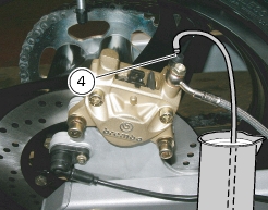
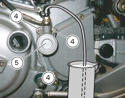
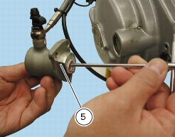
Open the bleed valve by one fourth of a turn and operate the brake lever (or pedal) several times until the fluid starts coming out of the bleed valve.
Pull the lever or pedal fully in and slacken the bleed valve by at least one fourth one fourth of a turn.
Allow several seconds and then release the lever (or pedal) gradually and close the bleed valve (2) or (4).
Caution
Do not release the brake lever (or pedal) until the bleed valve has been fully tightened.
 
Repeat the bleeding operation until air bubbles no longer come out of the plastic tube.
Bleed all bleed valves on the calipers one at a time.
 
Tighten the bleed valve (2) or (4) to the specified torque (Sect. C 3, Frame torque settings). Fit the protection cap.
Top up and fit the covers. Tighten the screws (1) onto the reservoir (A) and the cap (3) onto the reservoir (B).
Changing the clutch fluid
Warning
Clutch fluid will damage painted surfaces if spilled on them. In addition, it will cause severe injury if spilled on the skin or into your eyes. In the event of accidental contact with skin or eyes, wash the affected area with abundant running water.
 
Undo the screws (2) and remove the diaphragm cover (1) from the clutch reservoir (A).
Connect a clear hose to the bleed valve (3); put one end of the hose into a container on the floor.
 
Suck the oil up from the reservoir (A).
Fill reservoir (A) with fresh oil up to MAX level.
Pump up two or three times with the lever to pressurize the circuit.
Keep the lever pulled toward the handgrip.
Loosen the bleed valve (3) so that oil flows off.
Warning
When filling up, keep oil level above MIN mark to avoid air bubbles into the circuit.
 
Let oil flow off from the bleed valve (3) until of different color. Tighten the bleed valve (3) to the specified torque (Sect. C 3, Frame torque settings) and top up oil to correct level.
Draining the clutch circuit
Warning
Clutch fluid will damage painted surfaces if spilled on them. In addition, it will cause severe injury if spilled on the skin or into your eyes. In the event of accidental contact with skin or eyes, wash the affected area with abundant running water.
 
Slip off the protective cap to expose the bleed valve (3).
Connect a bleeder to the bleed valve (3) on the transmission unit.
Note
If you are using a commercial bleeder, follow the manufacturer's instructions.
 
Unscrew the bleed valve and pump the bleeder until all the fluid has fully drained off the circuit.
If you do not have a bleeder available, connect a piece of transparent plastic tubing to the bleed valve (3). Place the other end in a container on the floor holding used clutch fluid.
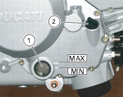
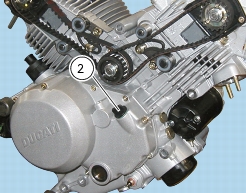
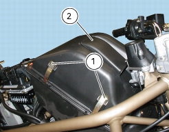
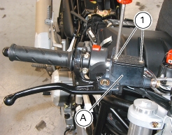
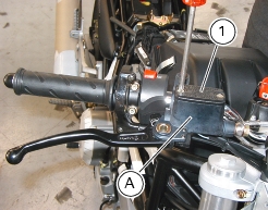
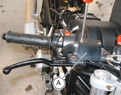
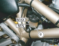
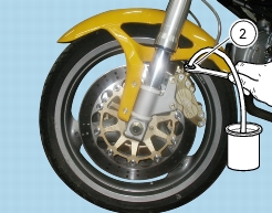
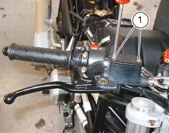
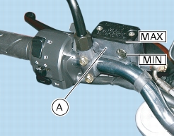
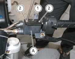
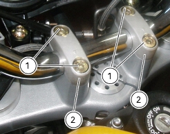
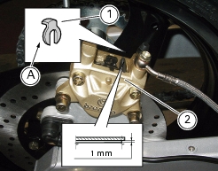
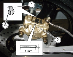
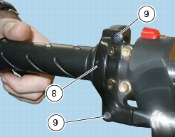
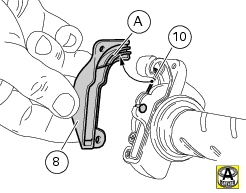
Unscrew the bleed valve (one fourth of a turn). Remove the filler plug (1) with diaphragm from fluid reservoir (A), loosening screws (2).
Operate the clutch lever until all the fluid has fully drained off the circuit.
To help drain the circuit fully, unscrew the three retaining screws (4) of the transmission unit and remove.
Withdraw the clutch transmission unit (5). Be careful of the O-ring (6) placed inside.
Push in the piston to expel all fluid inside the unit.
Refit transmission unit and tighten the retaining screws (4) to the specified torque (Sect. C 3, Frame torque settings).
Tighten the bleed valve to the specified torque (Sect. C 3, Frame torque settings).
Filling the clutch circuit
Warning
Clutch fluid will damage painted surfaces if spilled on them. In addition, it will cause severe injury if spilled on the skin or into your eyes. In the event of accidental contact with skin or eyes, wash the affected area with abundant running water.
 
Fill the reservoir (A) with specified fluid (Sect. C 2, Fuels and lubricants) taken from a sealed container.
Caution
During the next operation, the fluid level must remain topped up at all times. The end of the transparent plastic tubing must remain immersed in the discharged brake fluid at all times.
 
Operate the clutch lever several times to let the fluid reach all points of the circuit and expel any air.
Connect the bleeder to the bleed valve (3).
Note
If you are using a commercial bleeder, follow the manufacturer's instructions.
 
Pump with the bleeder and slacken the bleed valve (3). Ensure the fluid level never drops below the MIN level.
Repeat the bleeding operation until air bubbles no longer come out of the plastic tube connected to the bleed valve (3).
If you do not have a bleeder available, connect a length of transparent plastic tubing to the bleed valve (3) as outlined in the draining procedure.
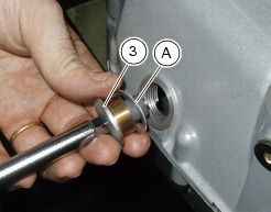
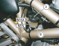
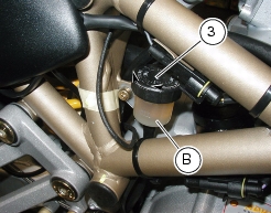
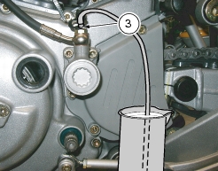
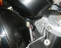
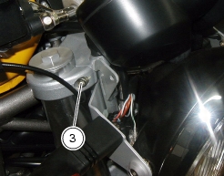
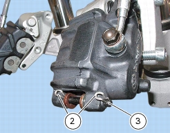
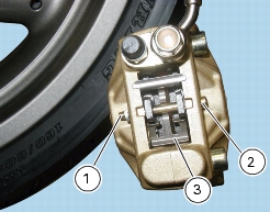
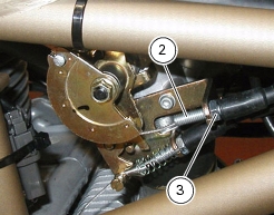
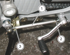
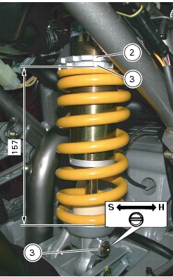
Open the bleed valve (3) by one fourth of a turn and operate the clutch lever several times until the fluid starts coming out of the bleed valve (3).
Pull the lever fully in and slacken the bleed valve by at least one fourth of a turn.
Allow several seconds and then release the lever gradually and close the bleed valve (3).
Caution
Do not release the clutch lever until the bleed valve has been fully tightened.
 
Repeat the bleeding operation until air bubbles no longer come out of the plastic tube.
Tighten the bleed valve (3) to the specified torque (Sect. C 3, Frame torque settings). Fit the protection cap.
Top up the clutch fluid up to 3 mm above the MIN mark.
Refit the diaphragm and cap (1) to reservoir (A), tighten the screws (2).
Adjusting steering bearings play
Excessive handlebar play or shaking forks in the steering head indicate that the play in the steering head bearings requires adjustment. Proceed as follows:
Loosen the four bolts (1), remove both clamps (2) and remove the handlebar.
Loosen the screws (3) on the steering head at the fork leg clamps.
Loosen the clamp screw (4) securing the steering tube to the steering head.
Tighten the ring nut (5) to the specified torque (Sect. C 3, Frame torque settings) using the tool part no. 88713.1058.
Tighten all the previously loosened screws to the specified torque (Sect. C 3, Frame torque settings).
Reposition the handlebar, fit the two U-bolts (2) and tighten the four U-bolt screws (1) to the specified torque (Sect. C 3, Frame torque settings).
Adjusting chain tension
Move the motorcycle slowly until finding the position at which the chain is tightest.
Place the motorcycle on the side stand.
Push the chain upwards with one finger at swingarm mid-length (see label).
The lower section of the chain should move by approx. 25 - 27 mm.
When required, adjust tension as follows:
Loosen nuts (1) at the wheel shaft ends.
Tighten (turn clockwise) the screws (2) equally on both sides of the swingarm to increase tension, or slacken to decrease it. In the latter case, you will need to push the wheel forward.
Caution
A slack chain will lead to early wear of the transmission components.
 
Check that the reference marks on both sides of the swingarm are lined up. This indicates perfect wheel alignment.
Tighten the nuts (1) onto wheel shaft to the specified torque (Sect. C 3, Frame torque settings).
Tighten the adjuster screws (2) to the specified torque (Sect. C 3, Frame torque settings).
Check that the nuts (3) that retain the rear chain sprocket to the flange are tightened securely. This can be done with the wheel installed, when you hold the bolts steady from the opposite end with an articulated 8-mm wrench.
If nuts (3) are replaced, apply some threadlocker and tighten them to the specified torque (Sect. C 3, Frame torque settings).
Checking brake pad wear. Changing brake pads
Warning
Brake fluid will damage painted surfaces if spilled on them. In addition, it will cause severe injury if spilled on the skin or into your eyes. In the event of accidental contact with skin or eyes, wash the affected area with abundant running water.
Caution
Please inform the Customer that new pads must be run-in carefully – in other words, the front brake must be used carefully - for the first 100 Km to allow the friction material to bed in completely.
Checking front brake pad wear
Loosen the screws (1) and remove the front brake calipers from the forks.
Make sure the groove in the brake pad friction material has not worn out.
Caution
If one of the pads is worn, change both pads.
 
Change the brake pads as follows.
Remove the split pins (2) from the pad retaining pin.
Force the brake pads apart to force the caliper pistons into their housings.
Withdraw the brake pad retaining pin (3) from the outside.
Release the worn pads (4) from the spring (5) and remove them.
Note
Change pads which are shiny or vitrified.
 
Fit new pads and their springs (5 and 6). Insert the centering pin (3) and lock it using the split pins (2).
Operate the brake lever repeatedly so that the pads bed in under the action of the brake pistons.
Check that the brake fluid level in the master cylinder reservoir is above the MIN mark.
If necessary, top up as follows. Turn the handlebar so that the reservoir is level.
Unscrew the two cross-slot screws (6) and remove the reservoir cover.
Remove the inner membrane (7) from the reservoir.
Top up to max level using the specified brake fluid.
Reassemble.
Checking rear brake pad wear
Check through the slot between the two caliper halves that there is at least 1 mm of friction material on the pads.
Caution
If one of the pads is worn, change both pads.
 
To change the pads, proceed as follows:
Remove the split pin (1) from the caliper retaining pin. The split pin is on caliper inner side. Force the brake pads apart to force the caliper pistons into their housings. Withdraw the brake pad retaining pin (2) from the outside.
Remove the brake pad retaining clip (3) from between the two caliper halves. Remove the worn pads.
Note
Change pads which are shiny or vitrified.
 
Insert the new pads and the clip (3). Insert the retaining pin (2) and push it fully home. Fit the split pin (1) with the end (A) pointing to the wheel.
Operate the brake pedal repeatedly so that the pads bed in under the action of the brake fluid.
Check that the brake fluid level in the master cylinder reservoir (4) is between the MIN and MAX marks. If this is not the case, unscrew the reservoir plug (4) and top up with brake fluid.
Note
In case of difficulties with pads replacement, remove the calipers (Sect. G 3, Removing the front brake system and G 6, Removing the rear brake system).
Warning
The brake calipers are critical safety components. Observe the instructions given in Section G “Wheels - Suspension - Brakes”. Be sure to tighten the brake caliper mounting bolts to the specified torque on refitting (Sect. C 3, Frame torque settings).
Adjusting the throttle and choke cables
Caution
Adjustment of the throttle and choke cables may affect the throttle body adjustments. Refer to “Adjusting idling condition”, Sect. D 5.
 
The throttle twistgrip must have a free travel of 2-4 mm (measured on the twistgrip rim) in all steering positions.
Fine adjustment can be made by turning the adjuster (1) on the twistgrip.
For larger adjustments of the throttle cable, use the adjuster (2) located on the RH side of the throttle body.
Remove the cap, loosen the lock nut (3) and turn the adjuster (2) to obtain the required play.
Tighten the lock nut and refit the cap.
To adjust the choke control cable, turn the control level on the handlebar until fully open and check that the plate (6) is touching the end stop.
In this condition, ensure that engine is at 2000 rpm. Turn screw (7) to adjust the rpm.
Likewise, loosen the lock nut (5) and work the adjuster (4) to adjust the throttle control cable.
Check for proper conditions of the outer sheaths of the throttle and choke cables at regular intervals. The outer plastic sheath should not be damaged or cracked.
To ensure smooth operation of these cables, grease the cable ends with the recommended grease at regular intervals.
Work the throttle or operate the choke lever to make sure core cable is sliding smoothly. If not so, change the cable.
To lubricate the throttle control, unscrew the two screws (9) and remove cover (8).
Grease the cable end (10) and the pulley.
Refit the cover with extreme care. Insert the cable (10) in the slider (A) of the cover (8).
Tighten the two screws (9) to secure the cover.
Adjusting the position of the gear change and rear brake pedals
The position of the gear change and rear brake pedals in relation to the footpegs can be adjusted to suit rider preferred riding position.
To adjust the position of the gear change pedal, proceed as follows:
Clamp the rod (1) and loosen the lock nuts (2) and (3).
Note
Lock nut (2) has a left-hand thread.
 
Fit an open-end wrench to the hexagon of the rod and turn the rod (1) until the gear change pedal is in the desired position.
Tighten the two lock nuts onto the rod.
To adjust the position of the rear brake pedal, proceed as follows:
Loosen the lock nut (4).
Turn the pedal travel adjuster screw (5) until the pedal is in the desired position.
Tighten the lock nut (4).
Operate the pedal by hand and check that there is 1.5-2 mm of pedal free travel before the brake begins to operate.
If this is not the case, adjust the length of the brake cylinder control rod as follows:
Loosen the lock nut (7) on the brake cylinder control rod.
To increase the amount of pedal free travel, screw the rod further into the fork (6). Unscrew the rod to decrease.
Tighten the lock nut (7) and check the amount of pedal free travel.
Adjusting the rear shock absorber
The adjuster (1) is on the RH side at the bottom end of the rear shock absorber, near the mounting point to the swingarm. This adjuster sets rebound damping.
The ring nuts (2) and (3) at the top end of the shock absorber are for external spring preload.
Turn the adjuster (1) clockwise for harder (H) damping and counterclockwise for softer (S) damping.
Standard setting:
from the fully closed position (clockwise) turn out the adjuster (1) by 18 clicks.
To change spring preload, slacken the upper ring nut (2) with a pin wrench. Tighten or slacken the lower ring nut (3) to increase or decrease preload.
Warning
Use the special wrench only to turn the ring nut for preload adjustment. When applying pressure to the wrench, ensure that wrench pin does not slip out suddenly from the slots in the ring nut. This could cause minor injuries to your hands. Do not use wrenches which are too small or have short handles.
Standard spring length: 157 mm.
Warning
The shock absorber is filled with high-pressure gas and might cause injuries if inexpertly dismantled.
Caution
When carrying a passenger and a load, set maximum spring preload for improved handling and to keep safe ground clearance. Set rebound damping accordingly.