|
4.3 -
|
|
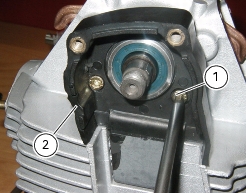
1
|
|
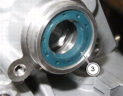
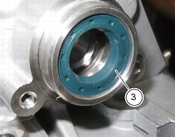
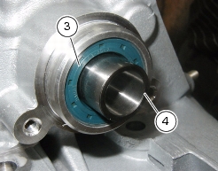
3
|
|
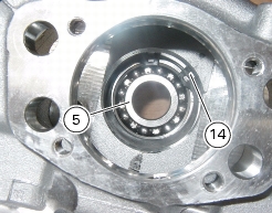
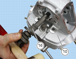
5
|
|
7
|
|
12
|
|
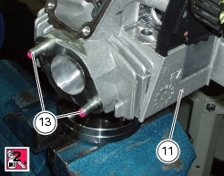
13
|
|
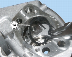
14
|
|
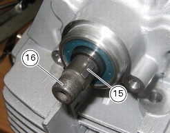
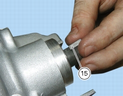
15
|
|
17
|
|
18
|
|
19
|
|
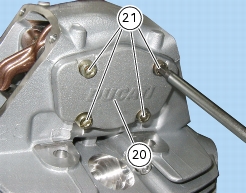
20
|
|
21
|
|
24
|
|
26
|
|
27
|
|
29
|
|
30
|
|
31
|
|
32
|
|
33
|
|
34
|
|
35
|
|
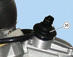
36
|
|
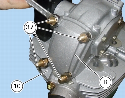
37
|
|
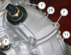
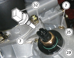
Disconnect oil temperature sensor from main wiring harness
|

|
Reconnect oil temperature sensor to main wiring harness
|