|
2
|
|
7
|
|
9
|
|
10
|
|
13
|
|
14
|
|
15
|
|
17
|
|
18
|
|
19
|
|
21
|
|
22
|
|
24
|
|
25
|
|
26
|
|
27
|
|
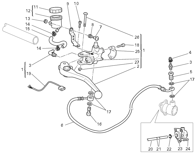
Remove the left hand guard/rear-view mirror assembly
|