4.1 -
1
2
3
4
Parts catalogue
Caution
Bold reference numbers in this section identify parts shown in this exploded view diagram. These parts do not appear in the figures near the text.
Checking and adjusting valve clearance
Note
For reasons of clarity, the figures show an engine block removed from the frame.
 
Take off the inspection cover on generator side and install tool part no. 88713.0123.
Turn the crankshaft until lining up the transmission pulley mark with the clutch cover mark.
Look through the inspection window in the generator cover. The flywheel mark and the cover mark (A) of both cylinders should be aligned.
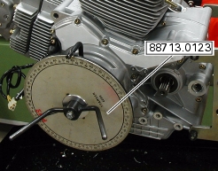
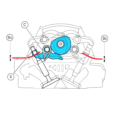
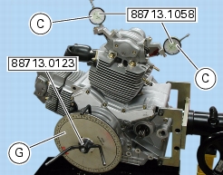
Reset the degree wheel of tool part no. 88713.0123: the horizontal piston is at TDC in the combustion stroke and therefore you can proceed with checking valve clearance on this cylinder head.
To measure valve clearance in the vertical cylinder, rotate the crankshaft counter clockwise through 270°. This will bring the vertical piston at TDC during the combustion stroke that is the correct position for checking valve clearance on this cylinder head.
 
Checking opening clearance (Sa) at intake/exhaust
To check opening clearance (Sa), slide a feeler gauge between opening rocker arm (B) and shim (3). Measured clearance must be within the specified limits (Sect. C 1.1, Timing/valves).
If the clearance measured is outside the specified limits, remove the opening shim (3) as described under paragraph "Removing the valves" (Sect. N 4.4), and replace it with a suitable one to reach the recommended assembly clearance.
Note
When performing this check and inserting the feeler gauge, pay attention to overcome rocker arm closing spring force to take up rocker arm operating play: for this purpose, ensure that shim can rotate freely.
Note
Spare opening shims are available in 1.8 - 3.45 size: the size is punched on the shim.
Checking closing clearance (Sc) at exhaust/intake
When checking closing clearance, use a screwdriver to overcome the preload of closing rocker arm spring, thus taking up any clearance between camshaft and rocker arm. Fit the feeler gauge between closing rocker arm (C) and shim (3): closing clearance (Sc) corresponds to gauge thickness when it allows the shim to freely turn, with no remarkable play.
Clearance must be within the specified limits (Sect. C 1.1, Timing/valves).
If not so, remove the closing shim (1) as described in paragraph "Removing the valves", Sect. N 4.4, and fit a shim of the adequate size to obtain specified assembly clearance.
Note
Spare closing shims are available in 2.2 - 3.1 size: the size is punched on the shim.
Refit the opening and closing shims as described in paragraph "Refitting the valves" Sect. N 4.4.
Checking valve lift
Fit dial gauge (C) part no. 88765.1058 into the hole of the head cover, as shown.
With the camshafts at rest position, take up valve opening clearance fitting a suitably sized feeler gauge between upper rocker arm and opening shim.
Note
This operation is best done using one dial gauge for the exhaust valve and another one for the intake valve.
 
Make sure the dial gauge fork is centered with valve axis and contacts the closing shim collar.
Set dial gauge to zero when the valve is fully closed.
Rotate intake camshaft so as to let intake valves lift fully.
Check that the reading on the dial gauge corresponds to the recommended value (Sect. C 1.1, Timing/valves).
Repeat same procedure for the exhaust valve, positioning the dial gauge mount to the opposite side of the head.
Reassemble following the same procedure given under “Checking and adjusting valve clearance”, previously in this manual.
Remove tools part no. 88765.1058.
Checking engine timing
Note
Engine timing should be checked after replacing such component parts as camshafts, valves or timing belt rollers or when overhauling badly worn engines.
 
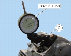
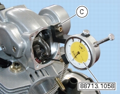
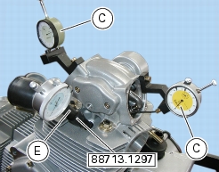
Remove the spark plugs and fit tool (E) part no. 88765.1297 in the spark plug hole and determine piston top dead center with gauges (C) part no. 88713.1058 and timing gauge (hub part no. 88713.0123 and degree wheel (G) part no. 98112.0002).
With the camshaft at rest position, take up valve opening clearance fitting a suitably sized feeler gauge between opening rocker arm and opening shim.
Check that camshaft can rotate. If it runs hard, use a smaller feeler gauge.
In this condition, the piston of the horizontal cylinder is at TDC with the valves fully closed - verify looking at gauge (E). Set dial gauges (C) to zero.
Set timing belts tension as described under Section N 4.2, Reassembling the timing belt tensioners.
 
Turn degree wheel (G) counter clockwise until dial gauge (C) placed at the exhaust end reads 1 mm lift. Check that valve angle reading in degrees on the degree wheel (G) is as specified (Sect. C 1.1, Timing/valves).
Rotate in the same direction until obtaining 1 mm lift on the intake end. Check degrees on degree wheel.
Rotate again until valve is fully closed during the combustion stroke.
Reverse rotation (i.e., turn clockwise) of degree wheel (G) until gauge (C) points 1 mm lift of intake valve. Check that degrees are as specified.
Rotate clockwise again until obtaining 1 mm lift of the exhaust valve.
Check degrees again.
Repeat procedure for vertical cylinder.
Allowed tolerance for measured values is ±3° with respect to specified values.
Remove the tools used to check engine timing.
1