|
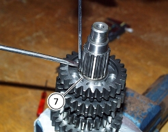
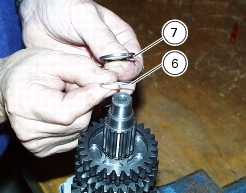
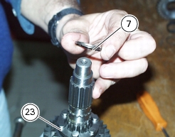
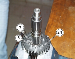
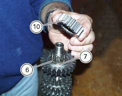
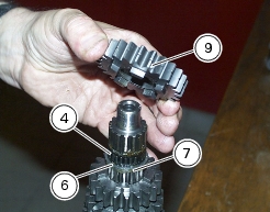
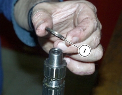
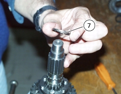
7
|
|
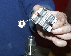
8
|
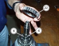
Driving gear - 3rd- 4th speed.
|
|
14
|
|
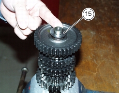
15
|
|
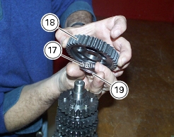
17
|
|
18
|
Driven gear - 1st speed
|
|
19
|
|
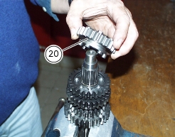
20
|
Driven gear - 5th speed
|
|
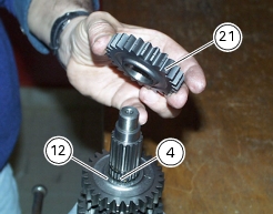
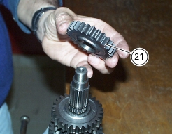
21
|
Driven gear - 4th speed
|
|
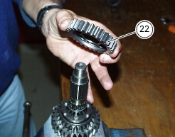
22
|
Driven gear - 3rd speed
|
|
23
|
Driven gear - 6th speed
|
|
24
|
Driven gear - 2nd speed
|
|
26
|
|
27
|
|
28
|
|
30
|
|
31
|