|
1
|
|
5
|
|
7
|
|
11
|
|
16
|
|
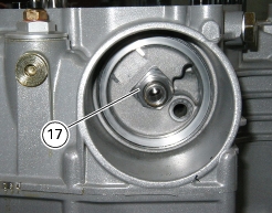
17
|
|
18
|
|
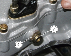
20
|
|
21
|
|
22
|
|
24
|
|
25
|
|
26
|
|
28
|
|
Remove the complete head unit with timing system
|
|


|
Refit complete head assembly and timing system parts
|
|
|
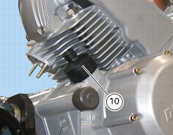
Remove the generator-side cover and the complete generator
|


|
Refit the generator-side cover and the complete generator
|