1 -
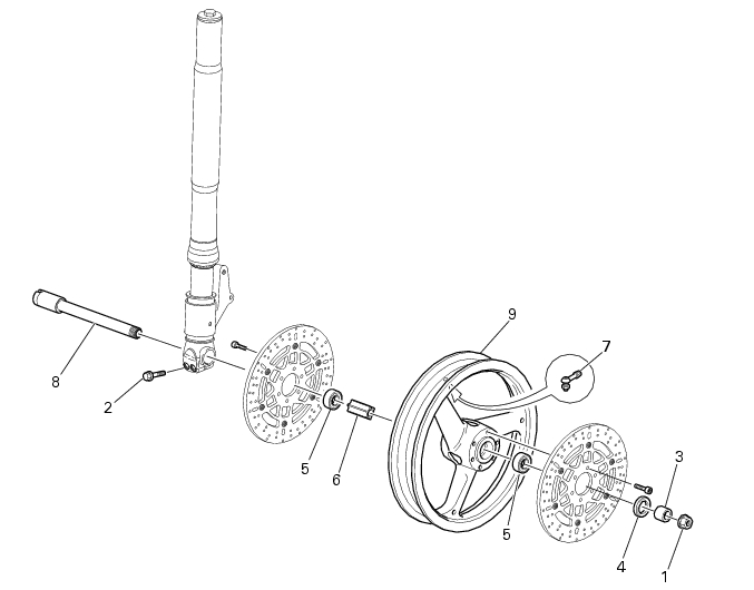
Front wheel
1
Nut
2
Screw
3
Spacer
4
Seal
5
Bearing
6
Inner spacer
7
Valve
8
Front wheel shaft
9
Front wheel rim
Spare parts catalogue
Front fork
Front and rear wheels
Caution
Bold reference numbers in this section identify parts shown in this exploded view diagram. These parts do not appear in the
figures near the text.
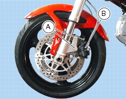
Removing the front wheel
Support the bike adequately so that the wheel to be removed is raised from the ground.
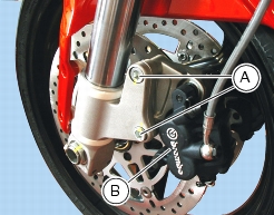
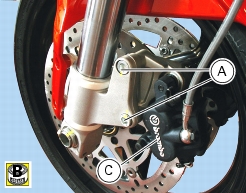
Loosen the two screws (A) securing the caliper to the fork leg and remove the front brake caliper (B).
Repeat the process for the other caliper.
Do not disconnect the hoses.
Warning
Do not operate the brake lever when the calipers are disassembled or fluid will leak out from the actuating pistons.
Note
The figures show the motorcycle with the front mudguard removed. However, the front wheel may also be removed with the
front mudguard in place.
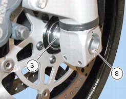
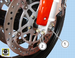
Undo and remove the nut (1) on the LH end of the wheel shaft.
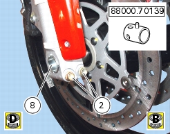
Loosen the shaft pinch bolts (2) on the fork legs.
Working from the left side, use a plastic hammer to knock the wheel shaft (8) out to the other side.
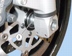
Slide the wheel out. Collect the spacer (3) on the LH side.
Overhauling the front wheel
Overhauling the front wheel bearings
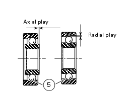
Before checking dimensions, check wear on wheel hub bearings. Check for wear by hand with the bearing in its seat. Clean and
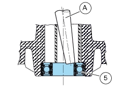
degrease bearing first. Turn the inner ring. Check the amount of radial and axial play. Excessive play will cause vibration and make the bike unstable. Change any badly worn bearings. To remove the bearings (5) from the wheel hub, follow the instructions below.
Position a drift (A) to the inner ring of the bearing (5).
Tap with a hammer until knocking out the bearing. Apply pressure at different positions to keep the bearing square during
removal.
Caution
Do not refit bearings once they have been removed. Before you fit new bearings, check that the seat is clean and free from
scoring and damage.
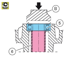
Grease the bearing seat and then push the bearing into the seat.
Warning
Do not smear the friction rotor of the brake disc with grease, as this will reduce braking efficiency. Using a tubular drift (B) which
only exerts pressure on the bearing outer ring, drive the bearing fully into its seat. Ensure that the spacer (6) is in place between the two wheel hub bearings.
Note
Wheels must be rebalanced after repair, maintenance and overhaul operations.
Overhauling the front wheel shaft
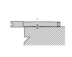
Check distortion of the wheel shaft.
Roll the shaft on a surface plate and measure maximum distortion using a feeler gauge (Sect. C 1.1,
Front wheel
).
Overhauling the front and rear wheel rim
After you have checked the bearings, check the rims as follows.
Visually inspect the rim for cracks, scoring and deformation; change the rim if damaged.
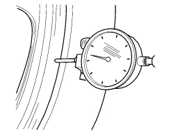
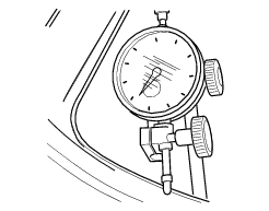
Insert the wheel shaft in the wheel and mount the shaft on two fixed reference blocks.
Using a dial gauge, measure rim run-out and out-of-round relative to wheel shaft axis (see Sect. C 1.1,
Front wheel
).
If the values measured are not within the limits, change the rim.
Refitting the front wheel
When through with the necessary inspections, refit the wheel as follows.
Grease the inside of the wheel hub.
Grease the wheel shaft (8) thread and shank.
Insert the complete wheel between the fork legs.
Warning
Position the front wheel; note that the arrow on the wheel rim indicates direction of rotation when running.
Insert the wheel shaft (8) from the right side.
Place the spacer (3) between wheel and left fork leg.
Apply service tool part no.
8000.70139
to wheel shaft (8).
Insert the shaft (8) fully home into the wheel hub; insert the peg of the service tool in the special notches at the bottom end of
the fork.
Grease the thread and underhead of shaft lock nut (1). Fit and tighten the lock nut on the end of the wheel shaft.
Tighten the nut (1) to the specified torque (Sect. C 3,
Frame torque settings
).
Grease the thread and underhead of the screws (A).
Tighten both brake caliper (C) screws (A).
Tighten the screws (A) to the specified torque (Sect. C 3,
Frame torque settings
).
Repeat the process for the other caliper.
Check that the brake discs run smoothly inside the calipers.
Before tightening the pinch bolts (2), lower the bike to the ground and press up and down on the handlebars to load the
suspension so the fork legs will become properly seated onto the wheel shaft.
Grease the pinch bolts (2).
Tighten the pinch bolts (2) to the specified torque (Sect. C 3,
Frame torque settings
). Tighten in a 1-2-1 sequence.