|
5 -
|
|
3
|
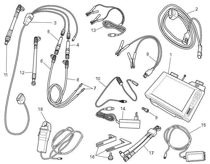
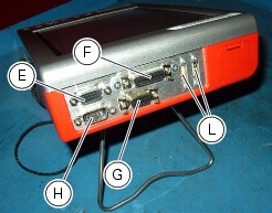
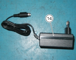
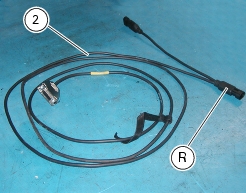
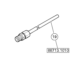
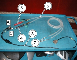
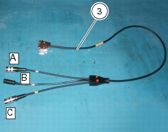
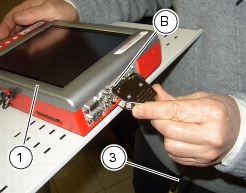
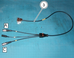
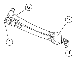
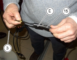
97900.0222 Power cord and diagnosis cable 1060838 (Measurement Module)
|
|
-
|
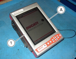
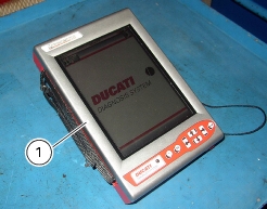
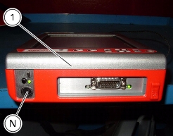
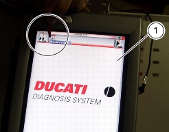
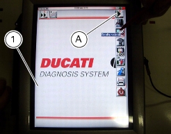
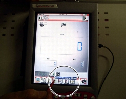
from the instrument own battery: the battery (Q) is located at the top of the instrument. Please refer to the "User's Manual" supplied with the DDS for instructions on how to use the instrument (1) with its battery and how to charge it.
|

|
-
|
|
-
|
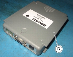
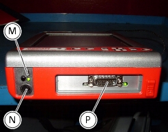
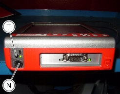
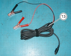
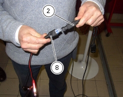
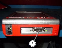
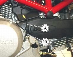
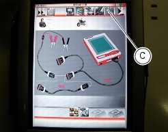
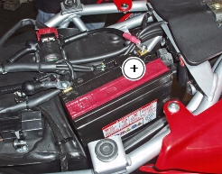
connecting the power and diagnosis cable (2) to instrument diagnosis connector (P); connecting battery adapter (8) to power and diagnosis cable connector (R) and then connecting the adapter to the vehicle battery.
|


|
-
|
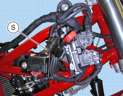
connecting the power and diagnosis cable (2) to instrument diagnosis connector (P); connecting power socket (S) to power and diagnosis cable connector (R).
|
|
-
|
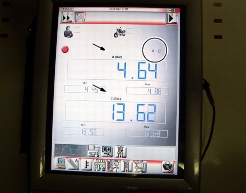
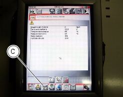
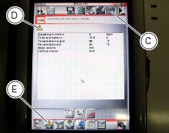
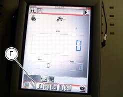
Parameter reading, such as engine rpm, coolant and air temperature, atmospheric pressure, throttle opening value, battery voltage, injection times, ignition advance values and so on.
|
|
-
|
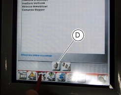
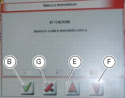
Active diagnosis. Enabling of ignition-injection system transducers to check for proper operation and correct control signal (fuel pump, ignition coils, rev counter, injectors and so on). This function also allows CO adjustment via software and electronic code entry to override the immobilizer.
|
|
-
|
Road test. This function allows you to store engine parameters within a preset rpm range. At the end of their acquisition, these parameters are then analyzed and displayed.
|
|
-
|
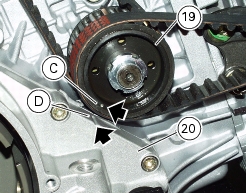
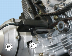
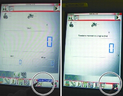
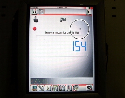
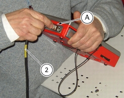
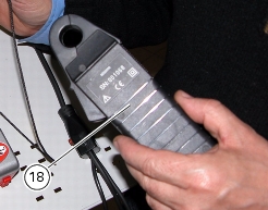
If connected to special feelers, the DDS can read voltage, current and temperature values as well as timing belt tension values and pressure values into oil and fuel circuits.
|


|
1
|
|
-
|
|
-
|
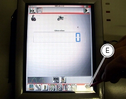
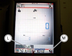
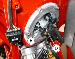
that engine is in the idle running conditions, i.e. that the closed throttle parameter on the DDS is ON.
|
|
1
|
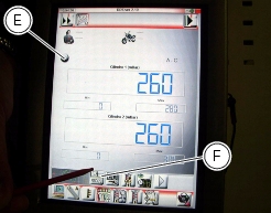
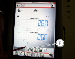
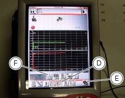
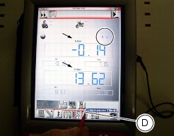
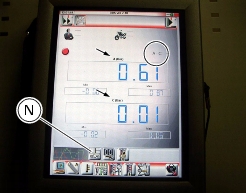
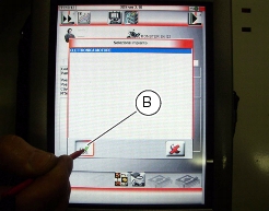
Check the lambda value λ on both cylinders. The following cases may apply:
|

|
2
|
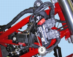
check the lambda value λ of the exhaust gas output by both cylinders, by “reading” with the exhaust gas analyser both cylinders at the same time. (You can do this by opening both analyser taps):
|
|
-
|
the λ (lambda) shall be automatically kept within the 0.95 - 1.05 range by engine electronic control system;
|
|
-
|


|
-
|
|
-
|


|
|
|
|
|
|
|
|
|
|
|
|
|
|
|
|
|
|
|
|
|
|
|
|
|
|
|
|
|
|
|
|
|
|
|
|
|
|
|
|
|
|
|
|
|
|
|
|
|
|
|
|
|
|
|
|
|
|
|
|
|
|