5 -
Checking the indicators and lighting system components
In the event of a fault, the internal connections of the device must be checked in all operating positions. To do this, disconnect the switch connector from main wiring (Sect. P 1, Arrangement of wiring on frame).
Test the switch using either an analogue or digital MULTIMETER (Sect. P 9, Test equipment).
Note
The same test may be done using the “DDS” tester (Sect. D 5, DDS diagnosis instrument).
Checking the left switch
Undo the screws (1) and disconnect the switch from the electric system to remove it.
Colours mentioned in the descriptions refer to the colour of wires from the switch and not to the colour of wires of the main electric system.
HORN button
Connect the terminals of a multimeter with Black/White and Black/Yellow cables to check for electric continuity, which must be available when HORN is pressed (see Sect. P 9, "Test equipment" on multimeter operation). When HORN button is pressed, resistance value taken by the multimeter should be close to zero and, if available, a continuity beep should be heard. When HORN is not pressed, the resistance value should be infinite (no continuity is available as electric contacts into the button are open) and no continuity beep should be heard. If the above does not apply, the part should be replaced.
Turn indicator switch
Connect the multimeter to Orange and Green wires from the turn indicator switch and check for electric continuity when operating the right turn indicator (Sect. P 9, "Test equipment" on multimeter operation). Repeat the above procedure for the left turn indicator but connect the multimeter with Orange and Grey cables. Colours mentioned in the descriptions refer to the colour of wires from the switch and not to the colour of wires of the main electric system.
Low and high beam (DIMMER)
Test method is the same. Connect meter as follows:
Low beam (LO)
(Blue/Yellow and Red/Black cables).
High beam (HI)
(Blue/Yellow and Red/Yellow cables)
Flasher (PASSING)
Check for continuity across the Red/Black and Brown cables.
 
Fit the left switch, tighten the screws (1) to the specified torque (Sect. C 3, Frame torque settings).
Checking the right switch
Undo the screws (1) and disconnect the right switch from the electric system to remove it.
Colours mentioned in the descriptions refer to the colour of wires from the switch and not to the colour of wires of the main electric system.
Engine stop button
Check for continuity between (Red/Black and Red/White) cables with a multimeter (Sect. P 9, Test equipment on multimeter operation). When the button is in RUN mode, electric continuity should be available between the two wires. When the button is in OFF mode, no electric continuity should be available between the two wires.
If the above does not apply, the ENGINE STOP switch is defective and should be replaced. Colours mentioned in the descriptions refer to the colour of wires from the switch and not to the colour of wires of the main electric system.
Starter button
Proceed as described for the engine stop button and check for continuity between (Blue/White and Black) cables when starter button is pressed (see Sect. P 9, "Test equipment" on multimeter operation). If the above does not apply, the STARTER button is defective and should be replaced. Colours mentioned in the descriptions refer to the colour of wires from the switch and not to the colour of wires of the main electric system.
Fit the right switch, tighten the screws (1) to the specified torque (Sect. C 3, Frame torque settings)
Checking front and rear STOP switches, neutral switch, oil pressure switch and clutch switch
STOP switches
Check for electric continuity (Pos. A) between the switch terminals of front STOP switch (1) and rear STOP switch (2) with a multimeter (see Sect. P 9, "Test equipment", on multimeter operation) when either front or rear brake is enabled. No electric continuity should be available when brakes are not enabled (Pos.B). Replace the checked part if proves to be defective.
Neutral light
Proceed as follows to check the neutral light switch (3):
The neutral light on the instrument panel does not turn on.
Remove the electric terminal connected to the neutral switch. Position the ignition key to ON to switch on the instrument panel and ensure that the light turns on when the terminal is grounded. If the light turns on, the neutral switch should be changed. If the light stays off, turn the ignition key to OFF to switch off the instrument panel and check for electric continuity between neutral switch and engine control unit with a multimeter.
 
The neutral light on the instrument panel is permanently on.
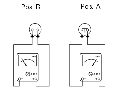
Position the ignition key to ON to switch on the panel and remove the electric terminal from the neutral switch. If the light turns off, the neutral switch should be changed. If the light stays on, turn the ignition key to OFF to switch off the instrument panel and use a multimeter to check whether the section between neutral switch and engine control unit is grounded.
Oil pressure sensor
Proceed as follows to check engine oil pressure sensor (4) for proper operation.
Use the DDS to check that oil pressure into engine oil circuit complies with the specified values (Sect. D 5, Checking engine oil pressure).
If engine oil pressure value is outside the operating range, check oil circuit parts and service as necessary.
If engine oil pressure value is within the allowed operating range and the warning light "low engine oil pressure" on the instrument panel stays off, turn the ignition key to ON still with engine off, disconnect the electric terminal from the pressure sensor and ground it. If the warning light turns on, the sensor should be replaced. If the warning light stays off, use a multimeter and check for electric continuity in the section between sensor and warning light on the instrument panel. Check with ignition key positioned to OFF (instrument panel off).
If engine oil pressure value is within the allowed operating range and the warning light "low engine oil pressure" on the instrument panel stays permanently on, turn the ignition key to ON, start the engine and disconnect the electric terminal from the pressure sensor. If the warning light turns off, the sensor is faulty. If the warning light stays on, use a multimeter and check whether the section between sensor and warning light on the instrument panel is grounded. Check with ignition key positioned to OFF (instrument panel off).
Clutch switch
For the clutch switch (5), proceed as described for STOP switches (see beginning of this section).
Changing light bulbs
Replacing the rear turn indicator bulbs
To change the rear turn indicator bulbs, loosen the screw (1) and remove the cover (2).
The bulb (3) has a bayonet base: press and twist counter clockwise to remove. Fit a new bulb having the same rating of the burnt-out one. Press and twist clockwise until it becomes properly seated with an audible click.
Refit the light cover (2) and tighten the retaining screw (1).
Changing the front turn indicators
The front turn indicators (1) are built in the hand guard assembly (Sect. E 1, Removing the hand guard - rear-view mirrors) and in case of failure it is necessary to change the complete rear-view mirror/turn indicator assembly.