|
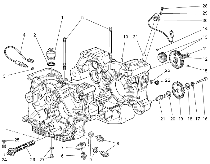
2
|
|
3
|
|
6
|
|
8
|
|
9
|
|
10
|
|
11
|
|
13
|
|
14
|
|
15
|
|
16
|
|
17
|
|
18
|
|
20
|
|
21
|
|
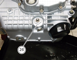
26
|
|
28
|
|
31
|
|
Remove the complete head unit with timing system
|
|


|
Refit complete head assembly and timing system parts
|
|