6.3 -
Clutch unit: primary gears
1
Nut
2
Seal
3
Primary drive gears
4
Bearing
5
Circlip
6
Bearing
7
Spacer
8
Safety washer
9
Circlip
Parts catalogue
1100
Clutch
1100
crankshaft
1100S
Clutch
1100S
crankshaft
Caution
Bold reference numbers in this section identify parts shown in this exploded view diagram. These parts do not appear in the
figures near the text.
Disassembling the primary drive gears
Operations
Reference - See Section
Remove the left fairing
E 2,
Removing the side fairings
Drain engine oil
D 4,
Changing the engine oil and filter cartridge
Remove the clutch cover
N 6.2,
Removing the clutch cover
Remove the clutch
N 6.1,
Disassembling the clutch
Note
For precision purposes, the figures show an engine removed from the frame.
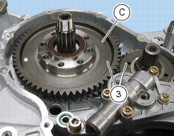
Remove the driven gear (C) of primary drive (3) complete with bearings and seal ring.
Replace gear inner parts with the help of a suitable drift (A) and a bearing surface (B).
Once the seal ring (2) has been removed, move the spacer (5) between the two bearings apart and tap from the inside to the
outside using a section of the inner race of the bearing (4) to be removed as bearing surface.
Tap onto different bearing points for linear removal.
Remove the bearing (6) in the same way.
Caution
If seal ring (2), special snap ring (9) and the spacer (5) have been removed, replace them. Snap ring and spacer should always be
replaced as a pair.
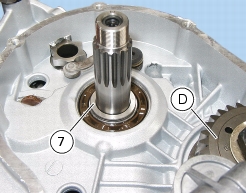
Remove the spacer (7) from the primary gearbox shaft.
To remove primary drive gear (D), first remove oil pump (Sect. N 2.1,
Removing the oil pump
).
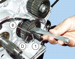
Unbend the safety washer (8) of the retaining nut (1) for the primary driving gear (D).
Fit the
88713.0137
onto the gear (D) and fit a pin in one hole for securing the engine to the frame to prevent rotation.
Loosen the retaining nut (1) for the driving gear (D) using a socket wrench of suitable length.
Remove the nut (1) and the safety washer (8).
Remove the driving gear of primary transmission (D) using the puller
88713.2092
; fit an aluminum or brass plate between puller screw and crankshaft.
Check that the crankshaft key (C) is in place.
Primary drive gear pair installation
– Meshing play inspection
Deeply degrease the crankshaft splined end of the crankshaft and its primary gear.
Fit the gear (D) onto the crankshaft with oil pump control sprocket facing the casing.
Temporarily fix in place with the washer (8) and the nut (1).
If a new primary drive gear (3) is fitted, check its meshing play.
Temporarily fit the gear (C) complete with bearings and seal ring onto the primary gearbox shaft and fit a dial gauge onto the
crankcase; position the dial gauge feeler onto a gear tooth.
Turn the driven gear (D) to match teething and check with the dial gauge that play ranges between
0.05
and
0.07
mm.
Check 16 points which are diametrically opposed on the gear.
If taken values are outside the allowed tolerance, change the position of the driven gear (C) onto the primary shaft leaving the
sprocket (D) untouched. If still outside the tolerance values, replace the primary drive gear.
When finished, finally tighten the nut (1).
Fit the tool part no.
88713.0137
onto the gear (D) and fit a pin in one hole for securing the engine to the frame to prevent rotation.
Tighten the nut to the specified torque with a torque wrench (Sect. C 3,
Engine torque settings
); turn clockwise.
Bend the washer (8) onto the gear (D) at milled zone and onto the nut (1) at a diametrically opposed position.
Fill the crankshaft with oil so that it is duly lubricated when started.
Fit the oil pump and check meshing play between oil pump gear and primary drive gear onto the crankshaft. (Sect. N 2.2,
Refitting the oil pump
)
Operations
Reference - See Section
Refit the clutch
N 6.1,
Reassembling the clutch
Refit the clutch cover
N 6.2,
Refitting the clutch cover
Fill oil into the engine
D 4,
Changing the engine oil and filter cartridge
Refit the left fairing
E 2,
Refitting the side fairings
1