
|
6
|
|
7
|
|
9
|
|
10
|
|
11
|
|
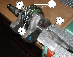
Remove the complete head unit with timing system
|
|
|
Remove the generator-side cover and the complete generator
|
|


|
Refit the generator-side cover and the complete generator
|
|
|
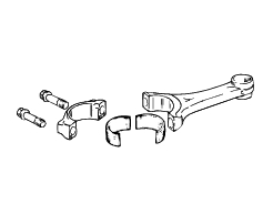
Refit the complete cylinder / piston assembly
|
|
|
Refit complete head assembly and timing system parts
|
|