|
1
|
|
2
|
|
7
|
|
9
|
|
10
|
|
11
|
|
12
|
|
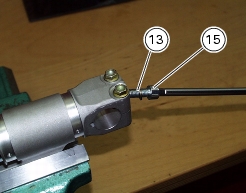
13
|
|
15
|
|
16
|
|
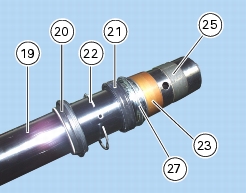
20
|
|
21
|
|
22
|
|
23
|
|
24
|
|
25
|
|
26
|
|
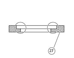
27
|