|
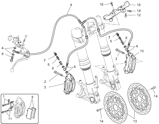
3 -
|
|
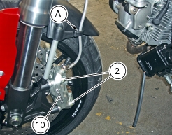
2
|
|
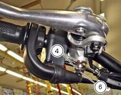
4
|
|
11
|
|
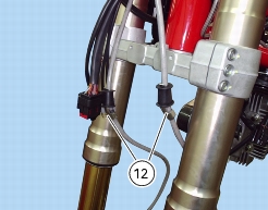
12
|
|
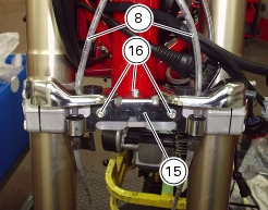
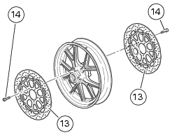
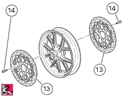
13
|
|
14
|
|
15
|
|
16
|