|
5 -
|
|
2
|
|
3
|
|
4
|
|
5
|
|
10
|
|
11
|
|
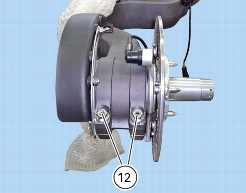
12
|
|
15
|
|
20
|
|
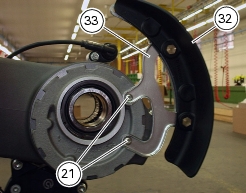
21
|
|
22
|
|
23
|
|
24
|
|
25
|
|
27
|
|
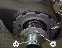
28
|
|
29
|
|
30
|
|
31
|
|
32
|
|
33
|
|
34
|
|
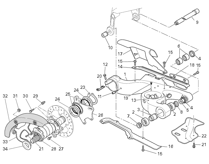
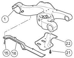
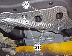
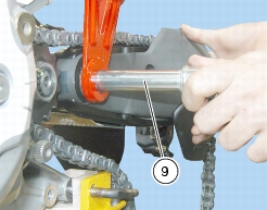
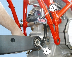
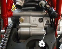
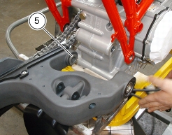
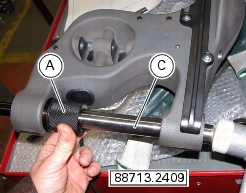
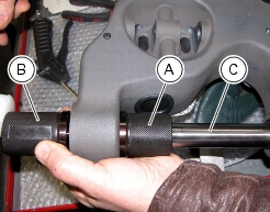
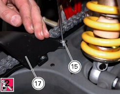
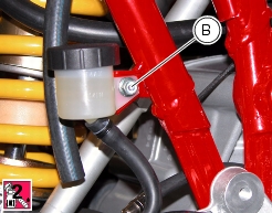
Disconnect the shock absorber and the linkage from the swingarm
|
G 7, Removing the rear shock absorber (1100S)
|


|
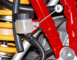
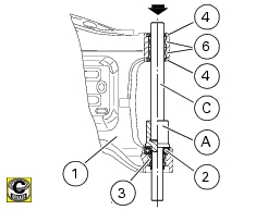
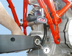
Connect the shock absorber and the linkage to the rear swingarm
|
G 7, Refitting the rear suspension (1100S)
|